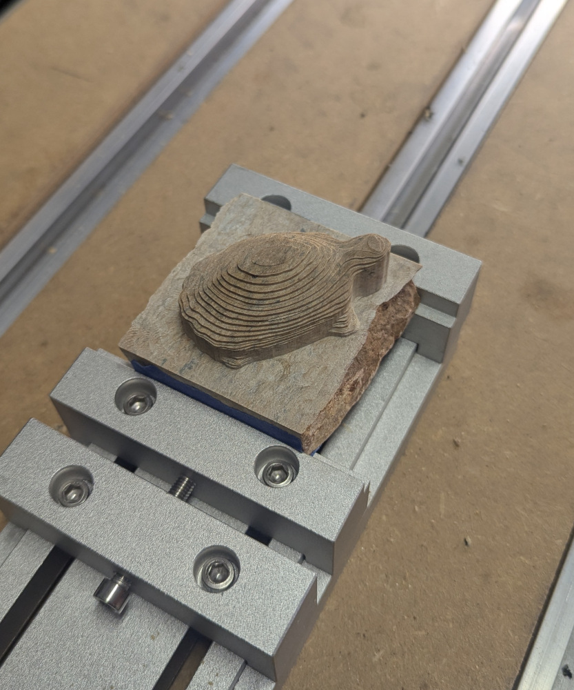
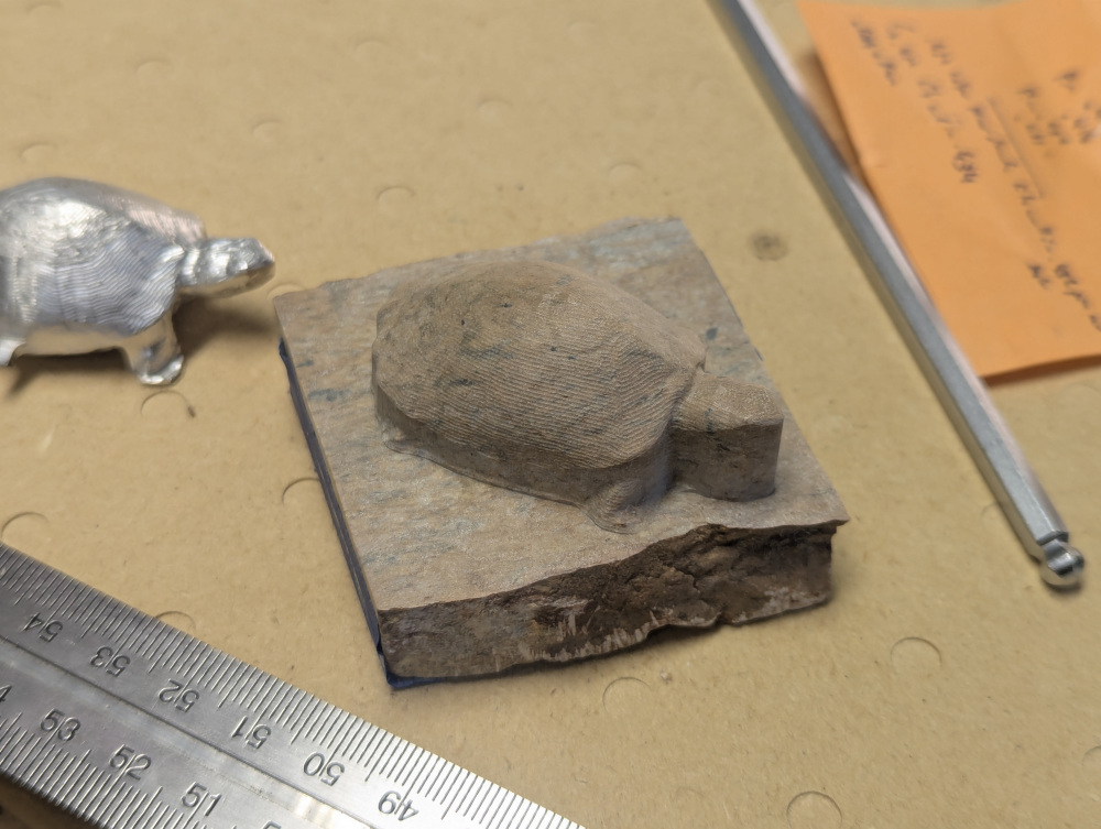
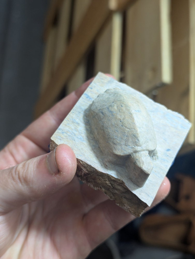
Soapstone is a soft stone with a pleasing handfeel that’s often used for carving into small statues and molds. I’ve been wanting to CNC machine soapstone for some time, but have always avoided it on my mill because I don’t want the dust to damage the mechanics. The Shapeoko has a good dust boot, so I decided to go ahead with it.
For this, I used a 3D adaptive toolpath with a 1/4″ endmill followed by a contour toolpath with a tapered endmill with a 1mm radius ball at the end. My surface speeds were 12,500 IPM and feeds were 0.001 IPT.
I could not grip the stock hard enough in the vise until I tried adding a layer of painters tape along the bottom edge of the stock, which is a trick we occasionally used at my previous employer.
Unfortunately, it would take a heroic effort to machine the bottom of this, which I did for the Aluminum turtle to the side. On that one, I left the model attached by tabs while machining the bottom.
The dust boot was so effective that there was no dust left as evidence.
I am writing software to generate drag knife toolpaths from SVG files. Drag knife cuts do not exactly follow the toolpaths, and if this is to be corrected, a way of predicting the cut path given a toolpath is nessesary. I have done the pen and paper math to get a differential equation the cut should follow given a toolpath and compared that prediction to actual use of the drag knife, finding good agreement. In a future post I will show how to generate toolpaths that produce cuts that closely match the inputted desired cuts.
For a drag knife, the blade is offset backwards from the center of rotation and is freely rotating. Cutting is done at the blade offset \(r\) from the center of rotation, and at the angle of rotation \(\theta\) :
$$\vec{x}_{cut} = \vec{x}_{toolpath} + (r sin(\theta), r cos(\theta))$$
When the tool is engaged and the center of rotation moves, the tool angle changes such that the cutting point moves the shortest distance. We can find the actual equation describing \(\theta\) by writing out the quantity to minimize \((|\frac{d\vec{x}_{cut}}{dl}|)\), and minimizing it by taking a derivative and setting it equal to zero. This gives:
where \(l\) is the length along the path and \(\phi\) is the path angle. We see that smaller blade offsets will cause \(\theta\) to track \(\phi\) more tightly, however this is an ideal case and more force will be required with small \(r\) to overcome the rotational friction of the drag knife, stretching the material to be cut. As the blade is held at an \(\approx45^{\circ}\) angle from vertical and the material has nonzero thickness there is also some range of cutting radii and the material or blade needs to bend for any turn.
I use the following block of code to predict the simulated path by Euler integrating the angle and substituting it into the equation of cut position:
# Given a tool path, predict the actual cut path def simulate(path, theta0):
# When not moving horizontally, just report previous movement direction if (cn[0] - cp[0])**2 + (cn[1] - cp[1])**2 <= 1E-3: phis.append(phis[-1]) else: phis.append(arctan2(cn[0] - cp[0], cn[1] - cp[1]))
# Angle only updates when the tool is engaged at Z = 0 if cn[2] == 0 and cp[2] == 0: thetas.append(thetas[-1] + (ln - lp) / BLADE_OFFSET_MM * np.sin(thetas[-1] - phis[-1])) else: thetas.append(thetas[-1])
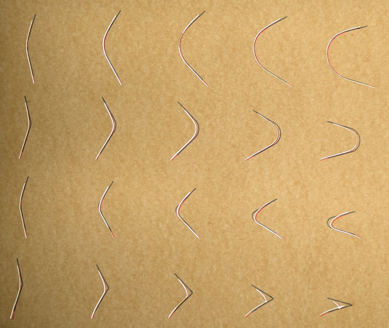
For a real test case, I scanned through arcs of different total angle and turning radius. I made gcode following the paths, and then traced out the desired cut in blue ink, the simulated cut in red ink, and switched to the drag knife and followed the desired cut’s shape. Below is a photograph of the results, taken from the paper on a light box (it is easier to see in person). Agreement is pretty good, including the weird reversal shape that happens in the bottom right corner. Where the simulated path is hard to see corresponds to places where the cut followed the simulated toolpath almost exactly.
I have recently aquired a Shapeoko CNC router, and with this comes the ability to do 4’x4’x4″ CNC work. I’ve wanted to be able to do CNC leather cutting for a while, but with my mill’s work envelope it never made sense before. To get this set up, I’ve mostly followed methods other people use.
For workholding, I made a vacuum table out of MDF, powered by a shop vac. This consisted of two MDF sheets with a plenum carved between them and supporting structures to prevent the top surface from bowing downward. The non-suction surfaces were sealed with polyureathane varnish. The MDF was permeable enough to apply the required hold-down force for my applications. However, it’s clearly much less good than my real aluminum vacuum table for milling.
Vacuum Table interior.
You can buy closed-cell performated foam material to improve sealing, and I tried using it but it was worse in this application.
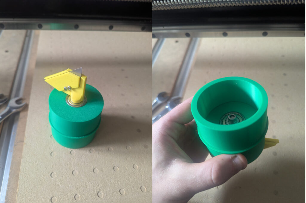
I designed and 3d printed my own drag knife. From a few design iterations it seems very important that the cutting axis of the knife closely aligns with the center of rotation, and that there is only an intermediate amount of rotational friction. The design uses a pair of bearings tensioned together with a bolt/lock washer combo. Adjusting the bolt changes the preload/friction.
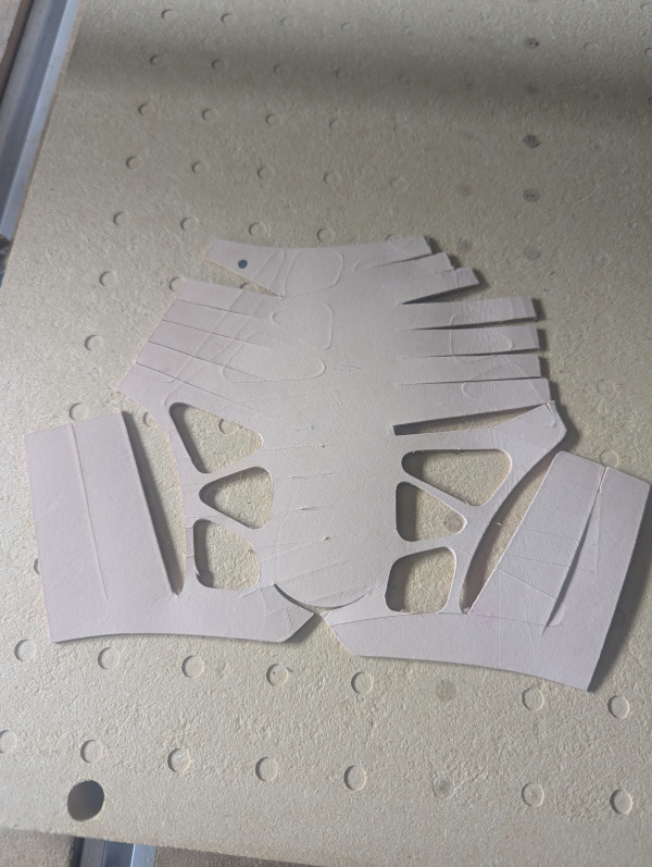
There will be a follow up post on software for generating toolpaths, but here’s a child-sized caligae as an example cutout. This was reused leather, so there are previous cut marks on the surface which didn’t go all the way through.
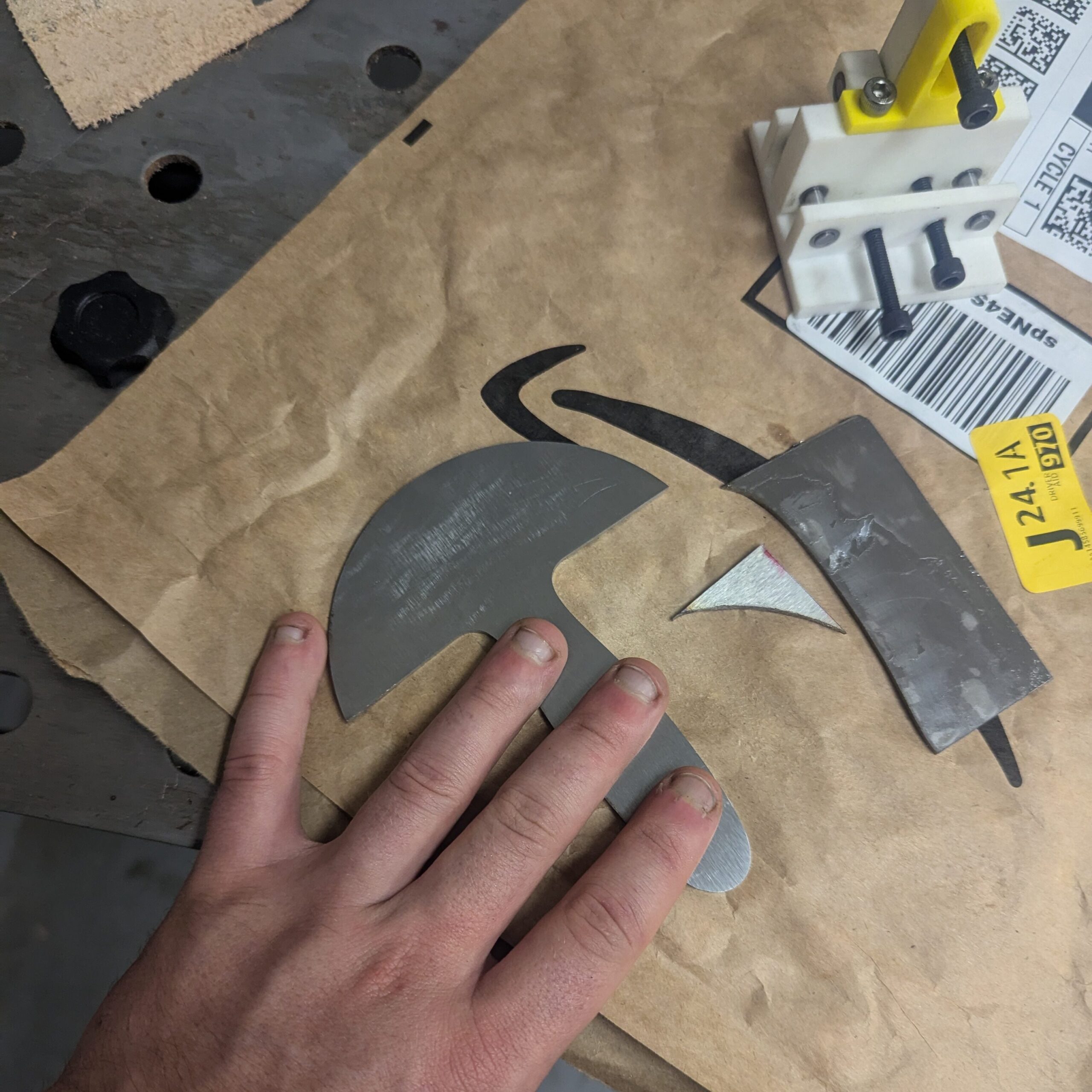
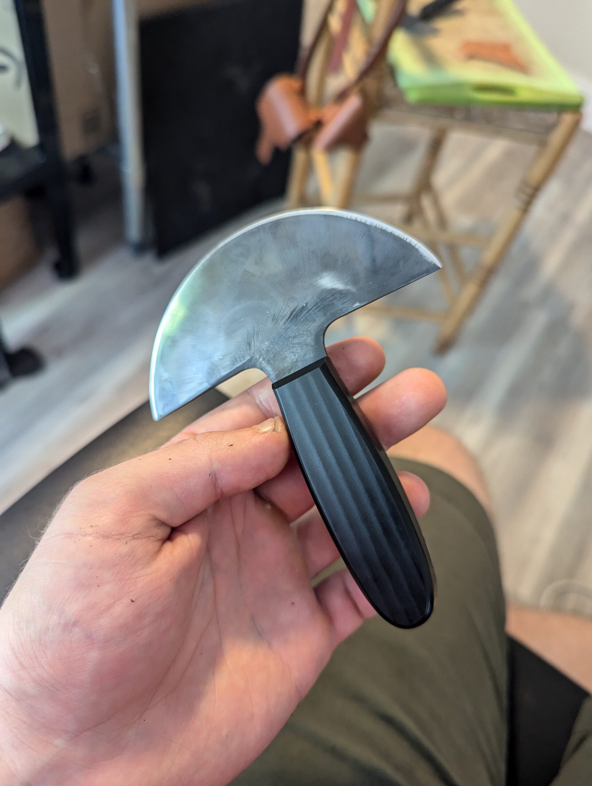
I made a head knife from a powder metallurgy steel (CPM 45VN) by machining the outline out of flat stock and then grinding the profiling with the help of an adjustable jig I made. For work holding, I glued the stock onto a plate and then, after drilling holes, bolted down the stock for more holding force. I was prepared for my hobby-ist grade mill to have problems but everything went beautifully.
Blade outline and adjustable grinding jig. The jig was too ambitious and in the future I would use ones with less adjustability.
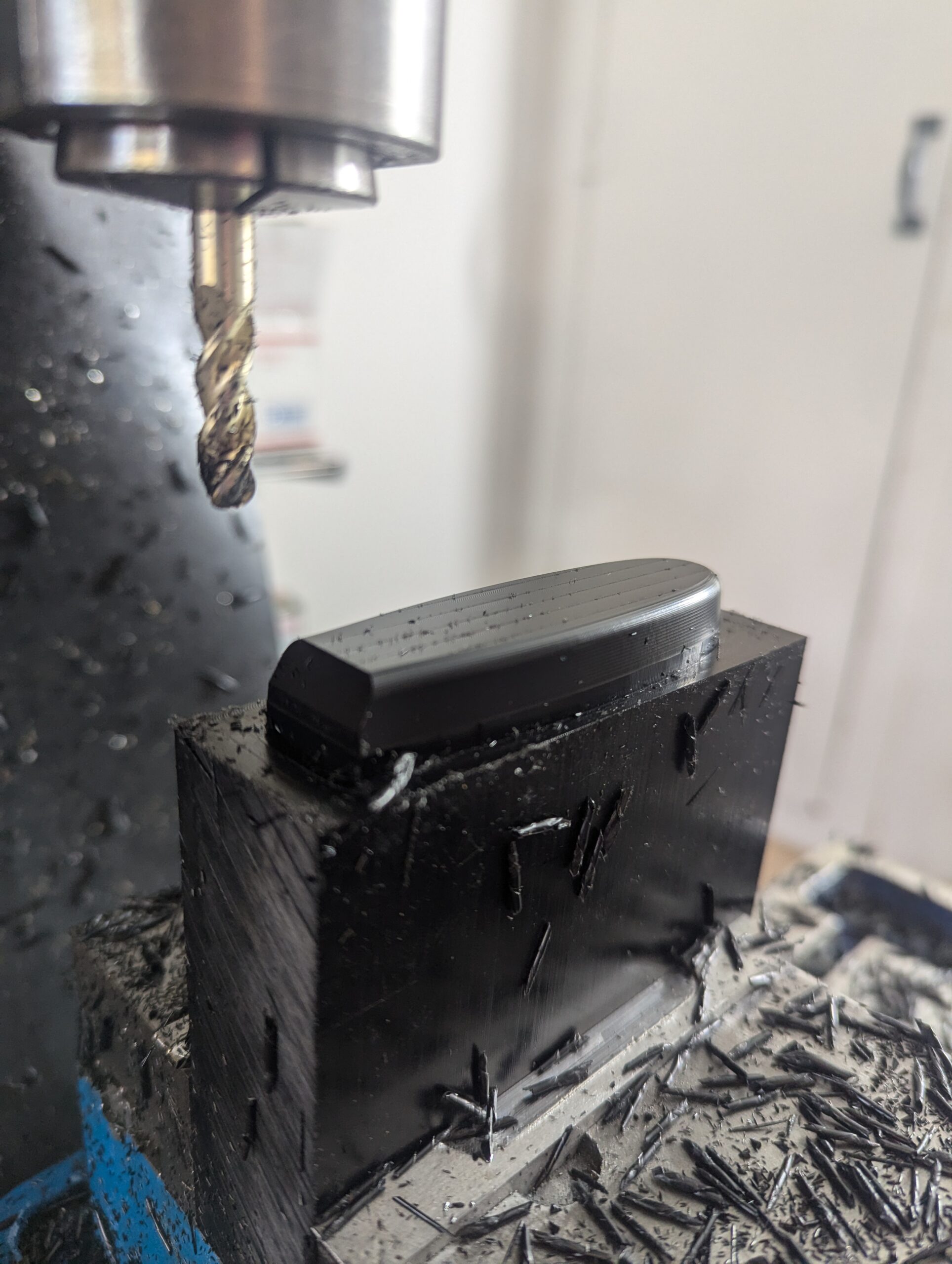
I machined the handle from Delrin. This was actually my first time working with Delrin and I was really happy with how it looks and feels. However, it’s definitely lacking in scratch resistance so the beautiful finish gets marred quickly. This was also my first project with a slitting saw, but now that I’ve used it once, I’ll probably use it often in future projects.
Handle half before cutting off with a slitting saw.The black coating on the knife is from the heat treat process
I recently bought a bambulab X1C 3d printer. This was inspired by how long it takes to machine many small parts for hobbies that could be adequately done with a 3d printer for much less effort. Design is much easier when you can iterate with 5 minutes of work per iteration and a few hours wait.
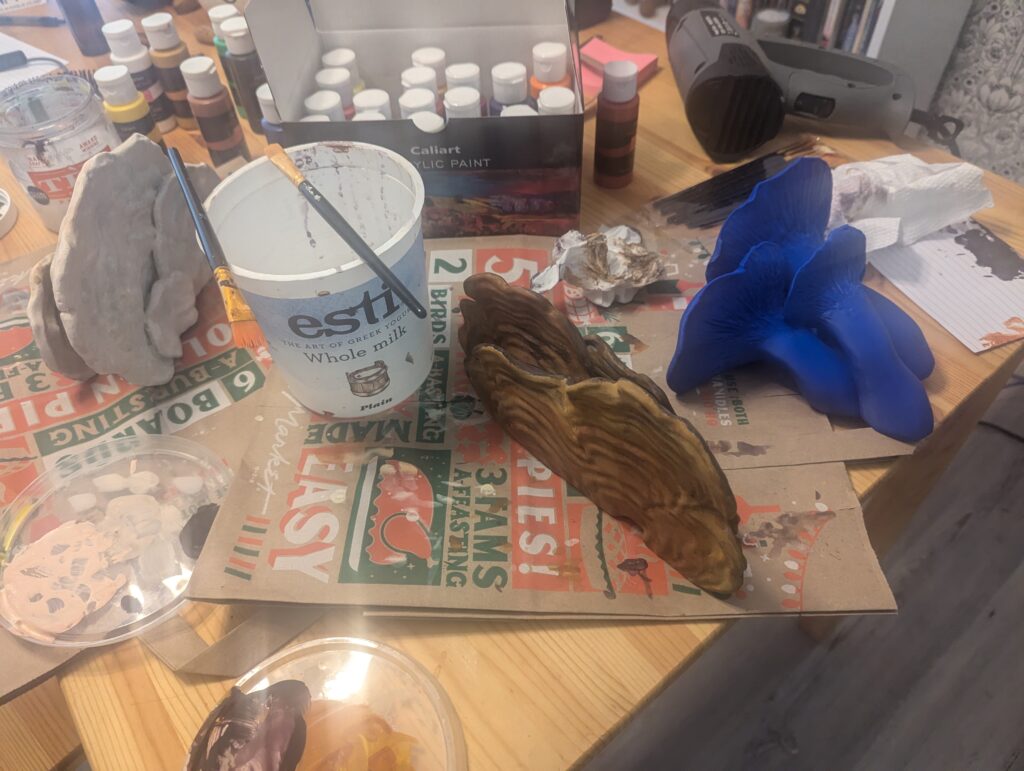
It’s amazing that we live in a society where the full paint set with brushes was only twenty dollars and will be delivered same day.
Work has been really busy recently so I decided to take a break from hobby engineering and do less ambitious fun things in my nights. I’ve been interested in learning to post-process 3d prints the way people do for props, and also for better 3d printed molds. This was kind of an experiment in that – I used a well recommended filler primer from Rust-oleum to try and hide layer lines and turn the 3d print surface into a good surface for painting. It seemed to work fine, but when I tried to make a nice layer-less surface for casting into it was clear how bad PLA is for sanding. There’s a Bondo product I’m going to try next.
Anyway, I like mushrooms and I found a guy on cults3d selling very nice mushroom models (https://cults3d.com/en/users/gazzaladra/3d-models), so I bought a bunch, printed them and spent a night painting them with my SO. Painting is harder than I remember; I haven’t painted since I was a child and mixed colors always turned out different from how I expected. However these are mushrooms so it’s realistic if they look a bit gross.
Getting the brush in to paint the deep crevasses was hardSomeday these will cover my entire houseStill waiting to paint this one.
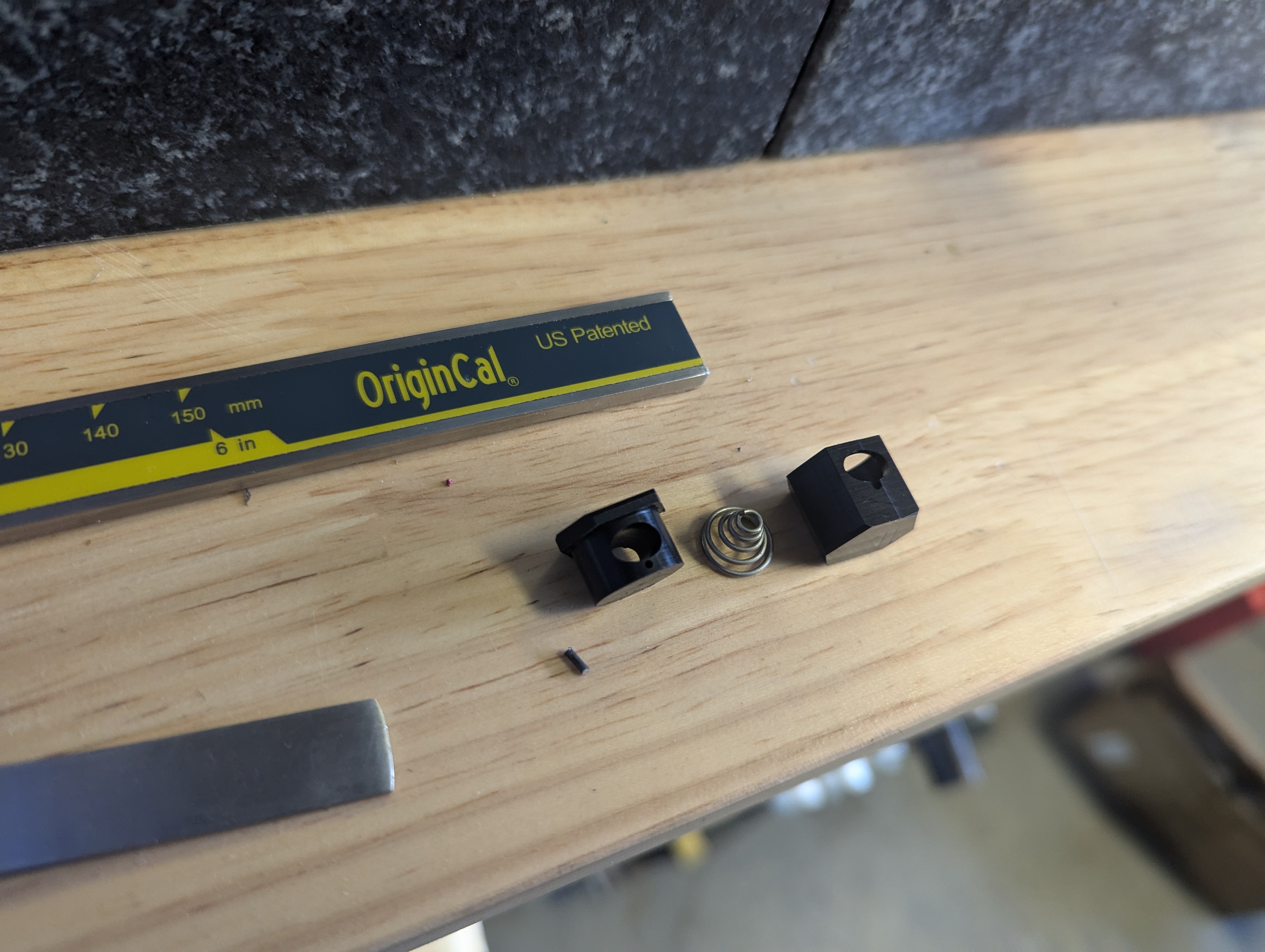
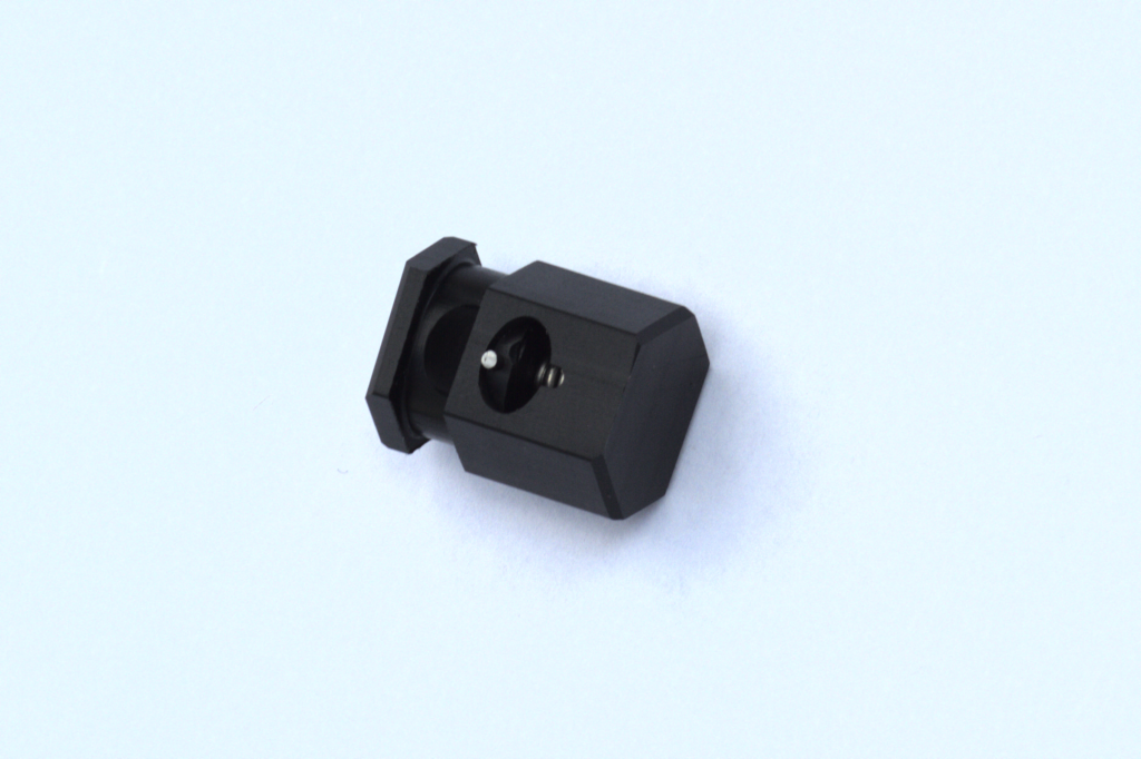
I have a repaired sweater with drawstrings and cord locks on the cuffs, which combines the comfort of long, loose sleeves with the ability to snug them up at my elbows for work. I thought it would be a neat exercise in engineering and art to design and make my own cord locks.
For the design, I looked at my personal cord locks, at cord locks online and their reviews. From the reviews I learned to be cautious about designing with too weak a spring. Aesthetically, I made a few CAD sketches until I found something I liked in a similar style as the belt buckle I made. A big concern of mine was that I would enjoy the appearance regardless of the position, and that all features would look intentional. For example, the alignment of the mobile part is maintained relative to the stationary part by having an elliptical track. One of my designs had a sort of terraced top made from the two parts so regardless of whether it was bottomed out or not, it would never transition between a flat top and a terraced top. For the spring, I found one on mcmaster that had the right range and enough compressive force.
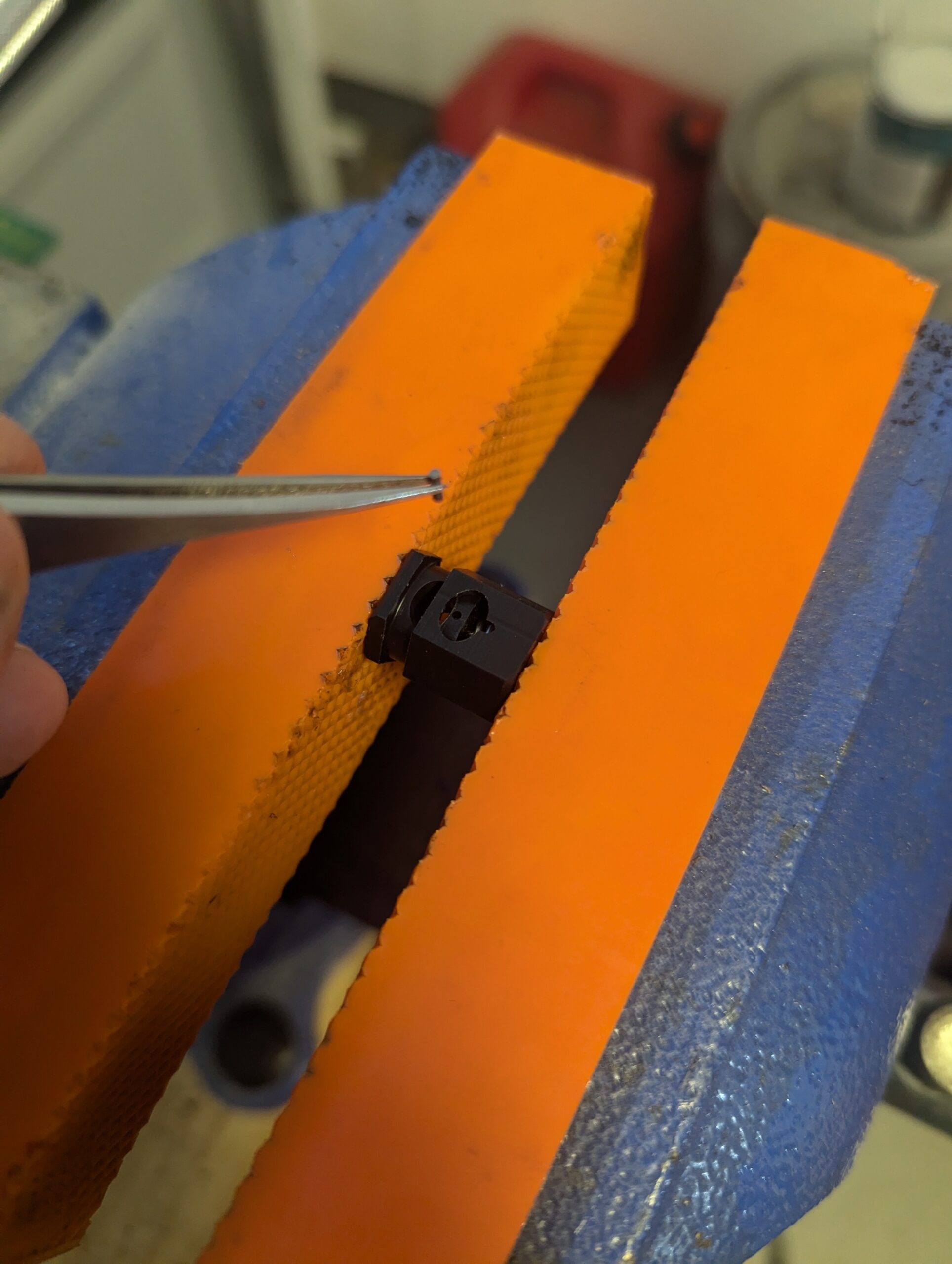
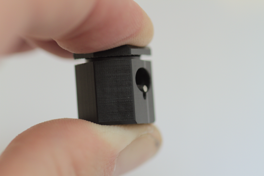
This is machined from delrin, with a stainless steel spring and a piano wire pin.
Inserting the pin without damage was a bit of a challenge
There are some things about the result which were unsatisfactory, which I’ve tried not to emphasize in these photos. They are all addressible with small manufacturing changes, so next versions will be better.
I made a belt with ansel.moe. I designed and made the buckle, and they incorporated it into a belt for me. I asked for a red utility leather I liked, and no liner or other belt features with the idea that we could redo everything better when I had used it enough to have opinions about what was good/bad from experience. Like many small machining projects, the hardest part was workholding, especially for the prong.
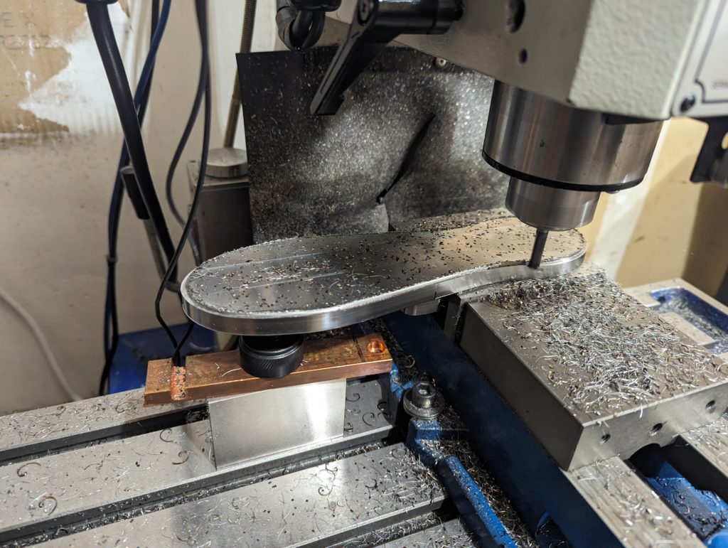
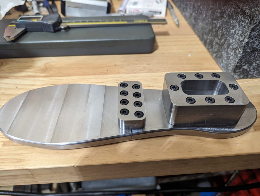
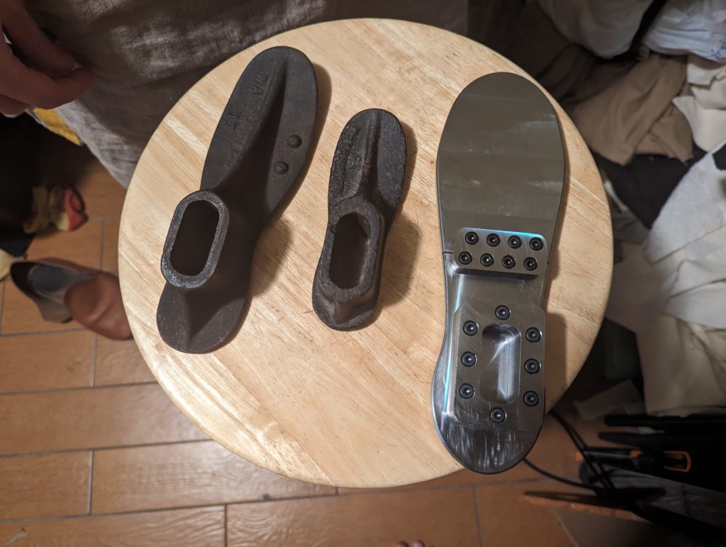
http://ansel.moe requested a larger anvil for driving nails into shoe soles. I had some 6x6x1/4″ (presumably) A36 lying around so I gave it a go in multiple parts. To get the outline I took a lot of profile measurements by hand from an existing anvil and scaled it up.
For workholding, I bolted the stock plate onto a sacrificial plate, drilled the stock holes and tapped them, bolted down the indiviual parts to cut out on the stock plate, and then milled them out down to the stock plate. When I had all the pieces, I bolted the post hole in alignment with the sole using an adjustable parallels and a 1-2-3 block, bolted the toe piece on, and clamped it in the vise by the post hole so I could contour the bottom. To help stiffen the overhang, I used a machinist jack, but cutting on the overhang was still noticably louder.
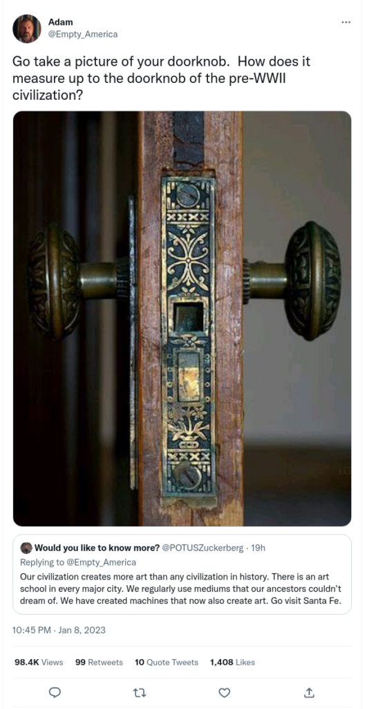
I get the impression that things are much less decorated than they used to be. This has been explained to me as because of the increased cost of labor, which has some issues but to me wins out over other explanations. Some other explanations I’ve heard are that people are overstimulated in life and don’t buy decorative stuff so they have a place to recover, that plainness and lack of decoration is the new class signalling, and that a different civilization is responsible for all the nice stuff we see historically but don’t see built any more. These may later explanations may be more correct but they are unverifyable, while the first points to a specific effect that is definitely true. An issue with the first explanation is that the ultimate cost of e.g. nice decals, impressions onto stamped metal, has also been made lower due to technology, but maybe less so than the thing itself. Regardless, I appreciate nice looking things and soulful things and want to live in a world with more of them.
Costs can be split into manufacturing costs and design costs. Something neat to me about additive manufacturing is that for a lot of methods, decorations are free, or atleast very low cost. The decorations can also be different for each object produced. For example, Desktop Metal has a binderjet printer that prints wood (sawdust+binder) and dyes the material to resemble different types of wood (Forust). Because it’s a binderjet printer, small model changes for e.g. fake engravings don’t affect print time or cost, and because the material is already volumetrially dyed having custom colorations and patterns and images should also come free. This is the best example, but all binderjet printers and resin LCD printers should have basically free 3D decorations, and many 3D printer methods that allow color have the same print time cost regardless of the color used. Of course, all these methods rely on 3D printing actually being a competitive way to design a mass produced product, but in my impression that’s already what a lot of 3D printing companies are betting on anyway. There are also many cases where literally the same object is sold from different places with several fold differences in cost so I think it’s very possible that most people would be willing to pay a small premium for custom items.
This leaves design costs. While I think there’s some human intervention required, there’s a lot of neat generative deep learning work that could be used to take the load off of human artists. For example, given a model of an object to print, a human probably needs to label visible surfaces vs. critical surfaces (surfaces which must remain unchanged for function). At the lowest end of engineering difficulty, aesthetic patterns or simple random textures/tilings can be applied. There are manufacturing methods which produce results like this already, where every customer gets a slightly different object in a nice way. At higher levels of engineering difficulty, generative deep learning models could produce stylized and themed decorations according to the desires of the consumer. I’m still thinking this side of everything through, so I’m collecting examples of technologies and art. While I have some experience making and training generator deep learning models, it’s not something where I’ve ever been happy with the result.
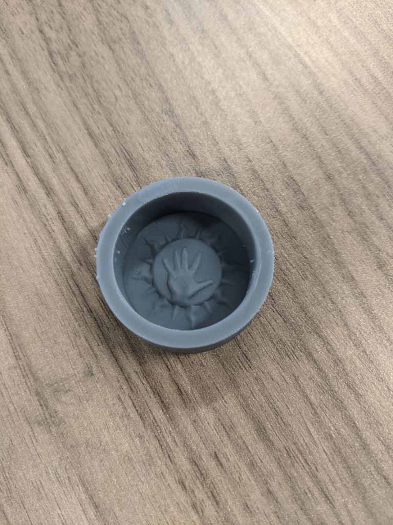
I was a bit interested in making a personal stamp (like for sealing letters), so I threw together a design in Blender, printed it, and cast it in silicone. Just a note, I was incredibly impressed with Blender’s sculpt mode-it felt like I was playing with actual clay, and no matter what I did the result was always a manifold mesh. I have plenty of experience where programs can’t even maintain manifoldness after boolean operations on relatively simple shapes.
For the stamp itself, I think I used smooth-on’s ecoflex gel (don’t remember now). Silicones are nice because they are generally non-stick, so no extra mold-release is needed. When cast, they often can transfer details finer than the eye can see and this level of detail is used for some types of lithography.
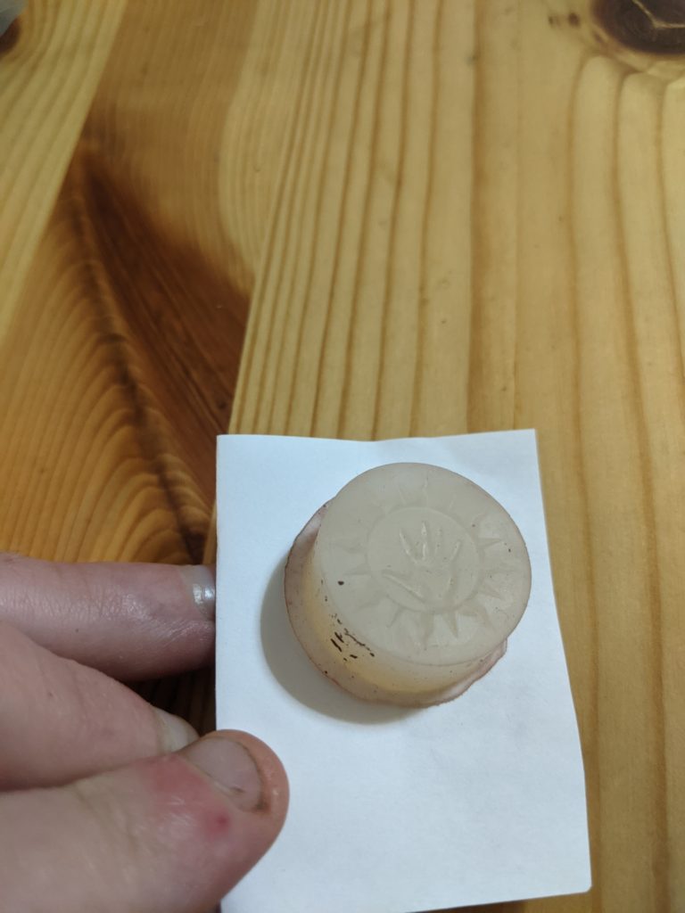
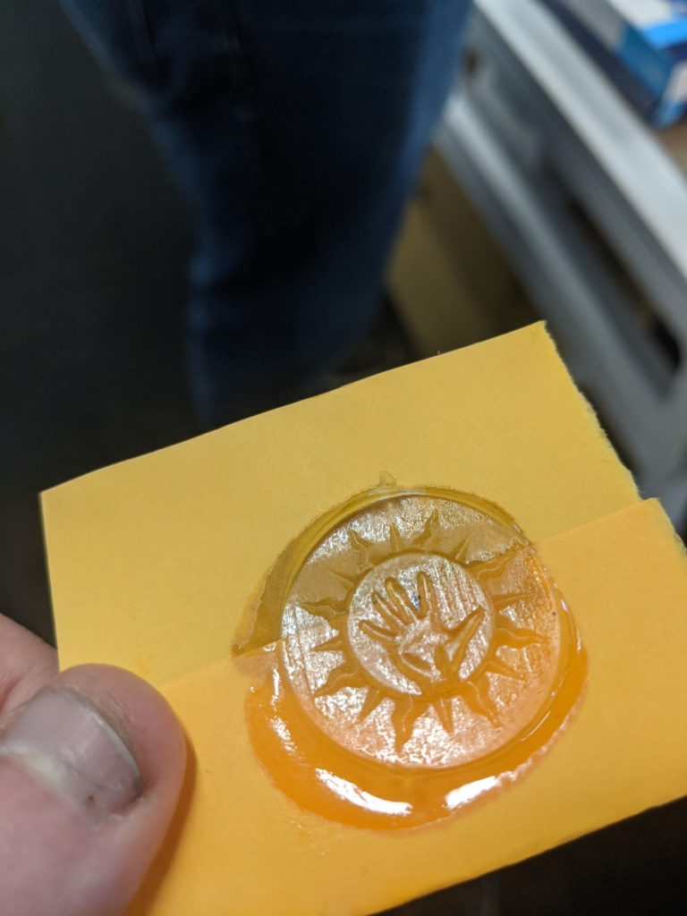
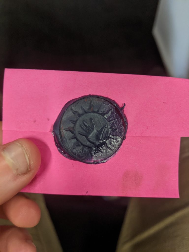
As 405 nm floodlamps and SLA resin were more common where I did this than waxes, I used resin first. I was pretty happy with the results.
Clear resinResin pigmented with lapis
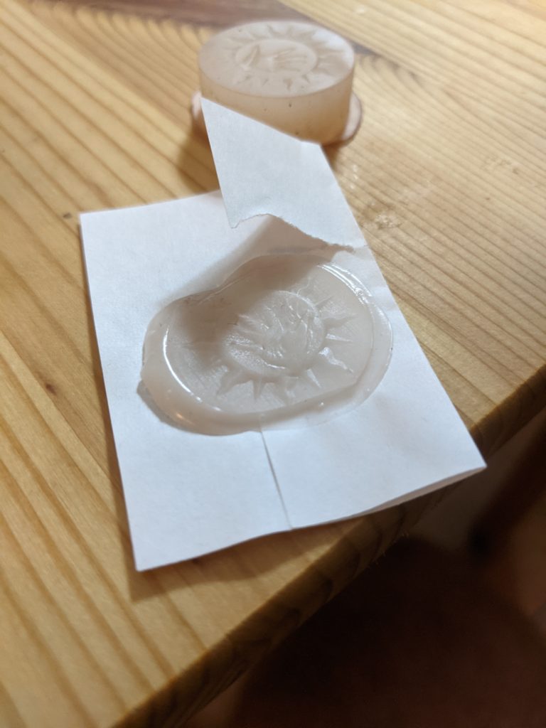
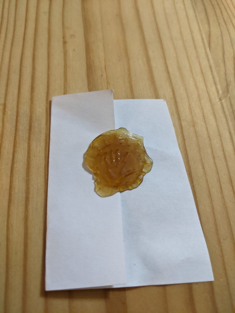
I also tried beeswax (not show), shellac and polycaprolactone, but wasn’t as happy with either of those.
PCL StampShellac
Traditionally, sealing was was made from shellac and beeswax with pigments. Modern sealing wax is literally hot glue. As I didn’t get anything melted to work well I wonder if it was because this used of a silicone stamp instead of a metal one.
I was thinking this would be neat to turn into a small self-contained device, with stamp material (resin or wax), stamp and activator (405nm light or heater). Maybe wedding planners would be interested in it.