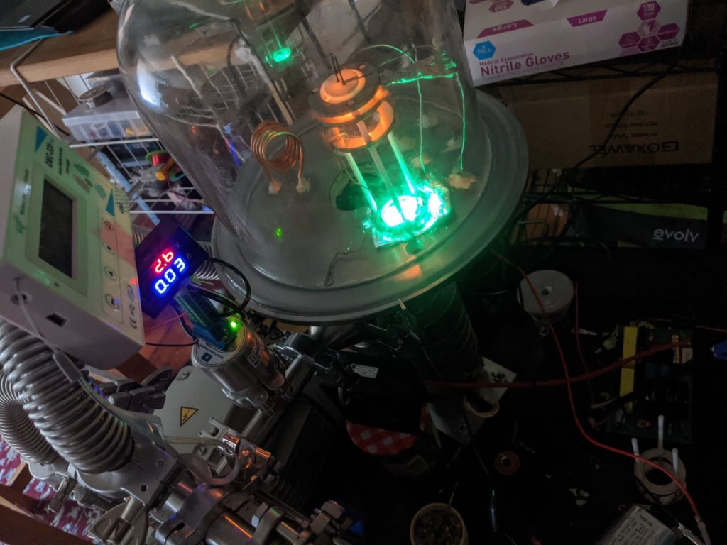
About 6 months ago I got a cheap vacuum chamber and pump made for degassing rubbers, added some electrical feedthroughs, and had a lot of fun with it (mostly making glow discharges, but I’ve also gotten steel to melt and some low quality coatings on glass). It looks like a factory-reject soup pot with a half inch polycarbonate lid and gasket.
More recently, I’m trying to make a cathode ray tube as for an old fashioned oscilloscope display. This doesn’t need to be good; I will be happy if I can get a bright dot on a screen in a which can be moved electrically. I’m approaching this with incredible naivety because a) this is a hobby project and hobby projects are meant to be fun and b) I want to develop techne and not episteme.
One of the nice things about this project is that there’s a good roadmap:
Working pressure sensorWorking diffusion pump (backing pressure below 1E-1 torr)Working current off a cathode (>1ma)High enough vacuum for reasonable electron free path, low cathode damage from ion bombardment under high voltage and so on (<1E-5 torr)A phosphor screen with visible glow from electrons(<-completed so far, I technically have a cathode ray tube but it’s not a display)- Electron optics (wehnelt cap, electrostatic lens?) to form a small spot on the screen
- Beam steering
- Computer control?
This is also nice because achieving high vaccum opens up a bunch of neat physics demos. I’ve made a vacuum tube diode, but I could use the same setup to make a triode. In the near future I want get a demo of the photoelectric effect.
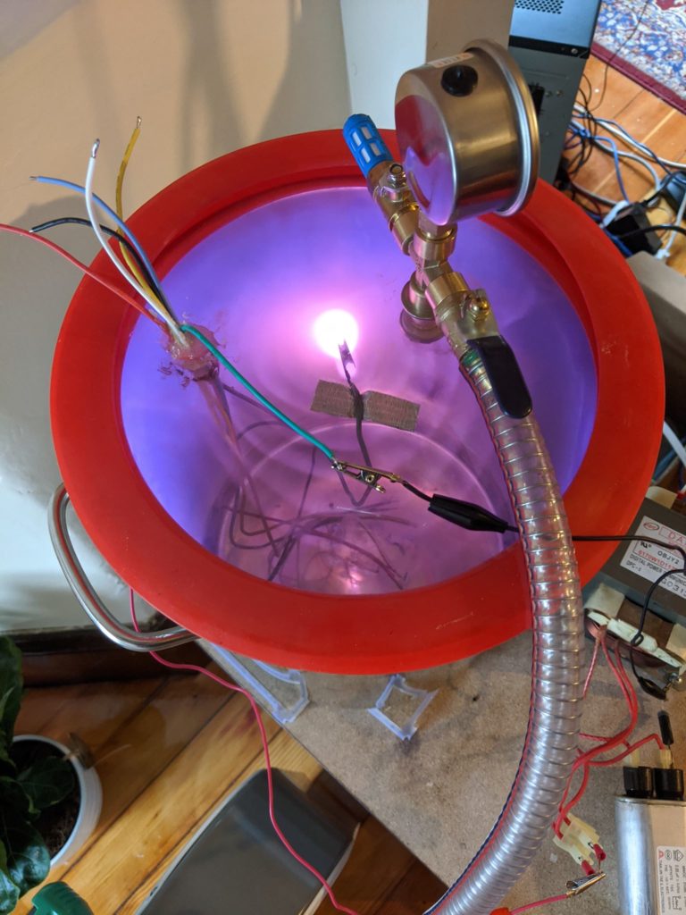
I bought a hybrid capacitive+pirani pressure sensor (HPS 901P) and 3d printed an adapter to measure the pressure in the vacuum chamber. The lowest pressure achieved with this old setup was a bit less than a torr (1E-3ATM) which is definitely not enough for a CRT. Not a surprise.
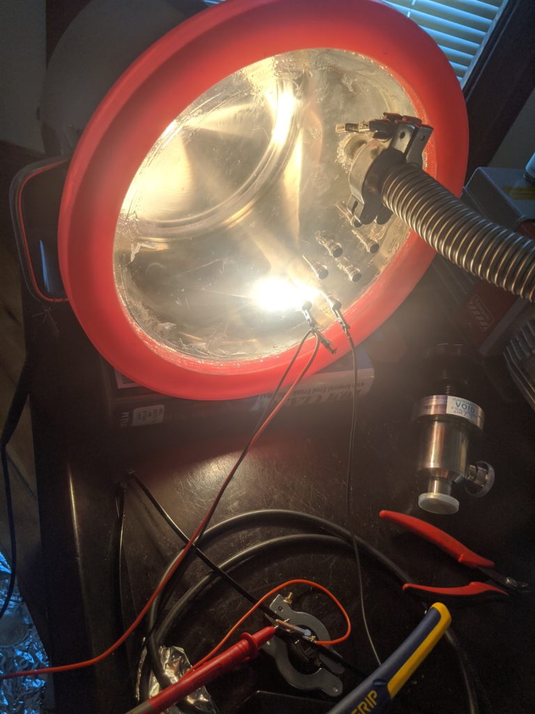
To achieve better vacuums, I bought a real rotary vane pump (edwards E2M-1), a small diffusion pump (varian AX-65), new diffusion pump oil, and a bunch of fittings/valves. I also bought a new chamber lid and made low leakage feedthroughs with M4 bolts sealed in with epoxy. When everything was right with this setup the pressure sensor read ~3E-2 torr from the roughing pump alone and ~3E-4 torr when the diffusion pump was turned on (the sensor was over the diffusion pump so this was an underestimate of chamber pressure). Closing the valve to the chamber would drop the registered pressure off the low end of the sensor, to <1E-5 torr. I experimented with baking the chamber (limited because the lid is polycarbonate), using different gaskets (several hand-cut silicone gasket thicknesses), and vacuum grease to cover up possible leaks.
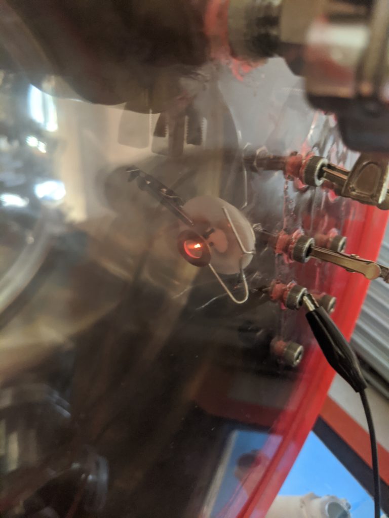
While this pressure wasn’t low enough for an electron gun, it was low enough to test cathodes. I biased the chamber positive 60V compared to a resistively heated tungsten filament and measured current from the filament to the chamber. The filament gave off up to 30mA, depending strongly on temperature. As a sanity check, I reversed the bias and saw very little current. Vacuum tube diodes worked this way.
Lanthanum hexaboride is a much better source of electrons than tungsten and works at lower temperatures, but it is much more expensive. I bought LaB6 powder and tested nichrome powdered with LaB6 with the above setup. There was a non-negligible current but less than the tungsten wire. I spent a lot of time trying to solidify it by sintering but this was fruitless.
There are cathodes built for electron microscopes, which are ideal because they are designed to have a small emitting area and have nice bases and wires. I ordered a lot with several used LaB6 cathodes and measured 1mA off of the only one in working condition.
Because this setup didn’t achieve high enough vacuums, I went back to the drawing board. I ordered a bell jar meant for vacuum demonstrations and got feedthrough holes cut into a steel plate at work. I keep on choosing designs which are large and transparent to minimize pain of setting up experiments. This steel plate has 10 holes for M4 stud feedthroughs, a 50mm hole to fit directly on the diffusion pump (to maximize conductance out), two holes to fit a coolant pipe in (for future projects) and a hole for a quartz window (for future projects). This time, I made sure that every vacuum facing surface would be either steel, glass or vacuum epoxy.
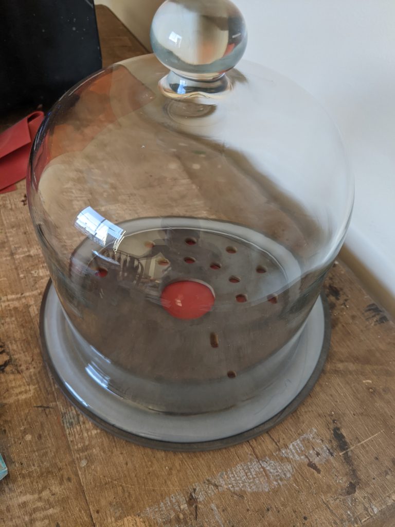
The ground glass bottom of the bell jar is nice because it’s flat (the soup-pot definitely is not), but it is only one of the mating surfaces. In an ideal world the bottom plate would be of stainless steel instead of hot rolled mild steel and machined flat before polishing. This would cost more than 20usd though. I removed the scale with HCl and hand polished.
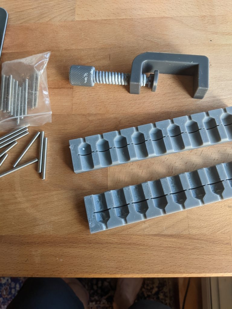
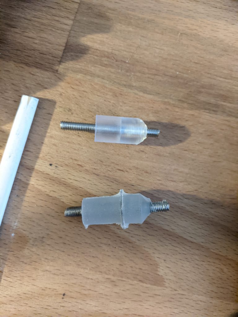
For the electrical feedthroughs I tried two methods. I 3d printed molds out of Formlabs grey resin and cast epoxy around the studs. Teflon spray lubricant was used as mold release, and the old vacuum chamber pot was used to degass the epoxy. This worked really well but I am an idiot and only printed 9 molds. I also directly 3d printed spacers to screw studs into, which is okay because they got coated in vacuum epoxy when they were installed to the vacuum chamber.
It took two tries to make the cooling coil, and the first version ended up causing a leak. The second version used soft copper and a 3d printed die to wrap the cooling coil around. I’ve tried to get inductively coupled plasmas from the cooling coil or by wrapping the chamber, but I can’t get a matching network to work using tools on hand. I also played with some AC glow discharges. I’ve read that plasmas can be used to speed up degassing of chambers, and watching the sensor while playing with glow discharges seems to confirm it.
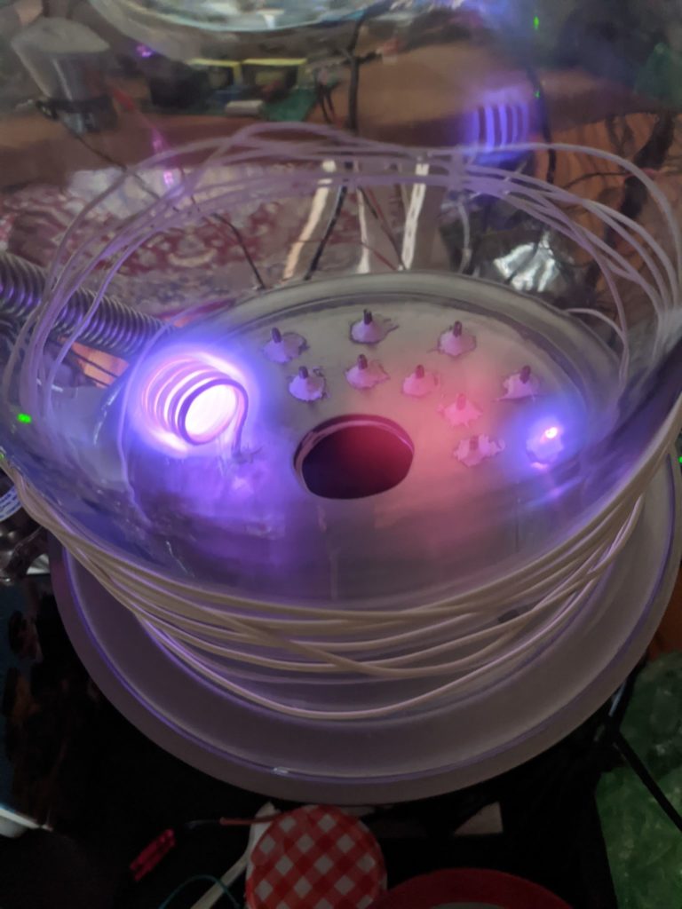
With this setup I was able to reduce the pressure to the bottom of the pressure sensors range, below 1E-5 torr, and measured no current when high voltage was connected to two feedthroughs. You may notice there is no gasket in the above picture. I wasn’t able to get any gaskets to work, and instead sealed the bottom with a very thin layer of vacuum grease.
A lot of phosphor materials used in real CRTs have elements which scare me. Luckily zinc sulfide, which glows in the dark, works. I made a screen by wrapping a glass slide in tin foil and coated it with zinc sulfide powder in gelatin water (apparently this was used to coat old photographic film). Accelerating electrons at this from the LaB6 cathode make it fluoresce. To drive the cathode and accelerating voltage I used a microwave oven transformer hooked up to a variac. This is convenient because it has both a high current filament supply for the cathode and a high voltage supply for the anode. The bad thing about this is that it ties the accelerating voltage to the heater current. I have an idea to seperate the two but it’s waiting on parts.
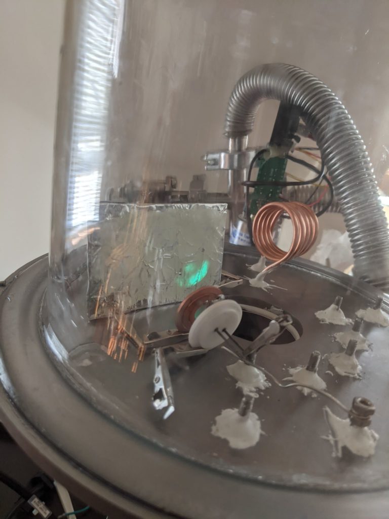
The screen glow varied with the variac setting, and danced around a bit with time. I assume this is from dirt on the cathode. The next step is to be able to generate a smaller point of light on the screen, which is in progress.
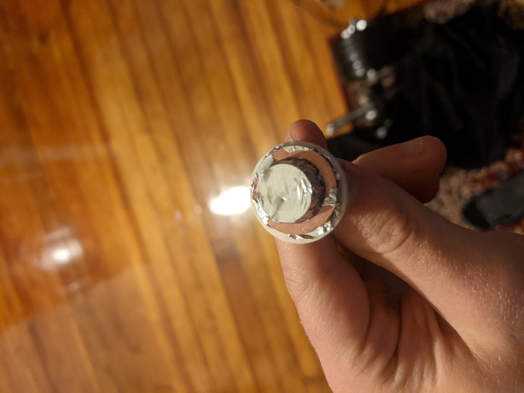
I’m going to make a mount to put the cathode and other electrodes on a set of rods to align them. There will be a pinhole on a flat surface at the negative cathode voltage right above the LaB6 crystal and flat with a larger hole at the accelerating voltage. I’m not entirely clear on how electrostatic lenses work in practice, so my idea is that if the electrons just ‘fall straight down’ it might still be good enough for a display.
