The chest strap is just a data logger, it reads from several sensors, logs the recorded data to a (double) buffer, and then sends batches of data off regularly over USB, BLE, or to the SD card. For analysis, it’s important that the data streams are aligned in time to a within decently short (<10ms) amount. It’s not mission critical to get every sensor reading, but the cleaner the timing is the easier later analysis will be.
So how can we check this? Two of the sensor ICs have FIFOs, which is nice because checking to see if data is lost is as simple as checking a FIFO overrun register. It also means that instead of communicating with the IC every sample period, communication can be delayed by a fraction of the FIFO size, so the time latency allowance is much higher. Those sensors each have their own clocks, so their sample rate deviation from nominal is going to be different from the microcontrollers time error, but this can be corrected by occasionally recording the microcontroller time and scaling the sample frequency to correct for the difference in clocks.
The ADC on the chest strap however has no FIFO, which means that the microcontroller has to communicate with it at 480Hz sample rate, giving us a maximum of 2ms where the microcontoller is doing other things (This isn’t exactly true, the data transfer can be set up to respond to the data ready pin with an interrupt, but it gets messier and the SPI mode has to be changed between reading from the ADC and the IMU and I’m not sure if I want to do that in an interrupt context). It also requires an external clock, so if attached to a timer pin on the microcontroller that would prevent drift between the sample rate and the microcontoller clock. The logging system collects timestamps with every N readings to check for missed readings.
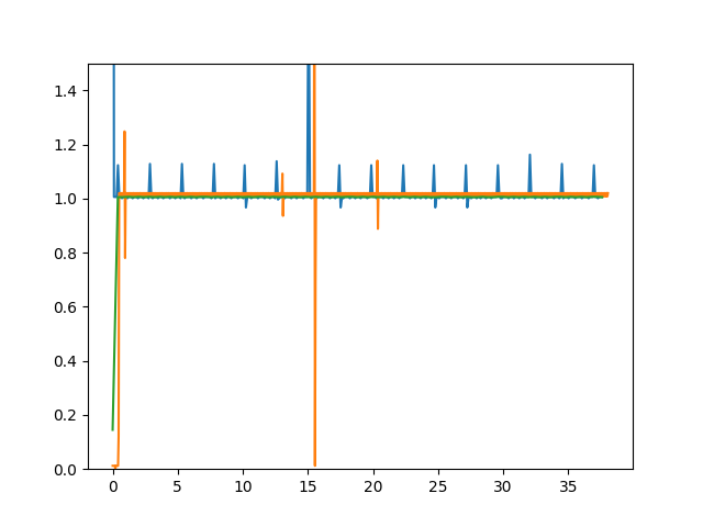
As a sanity check, I plotted the time difference between data reading time normalized to the ‘correct’ time. Below has the ADC (blue), IMU (orange) and PPG (green) data plotted, and we see regular spikes implying we are missing several ADC readings every ~1s. This corresponds to the SD card writes, and turning off SD logging gives an almost perfectly flat graph instead.
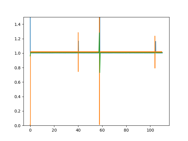
So, how do we make the SD card writes non-blocking? The logging software uses the FATFS file system library, and this was using the f_write function which returns the number of bytes written so it clearly must be blocking. I looked into this briefly, was overwhelmed, and then came back the next day and it was trivial. After opening the file with f_open, f_expand will make the file of X size of contiguous sectors. The f_expand documentation even shows how to write directly to sectors using the disk_write function. For this microcontroller, using the SDMMC interface, disk_write uses the BSP_SD_WriteBlocks function, which has a DMA equivalent. To write the data buffers I just call BSP_SD_WriteBlocks_DMA, after checking that the previous transfer is complete. With this change, the timing plot below is generated. The latency spikes are for closing and opening files, and I’m okay with having some lost data near file open and close.
As a further note, even f_write was not working reliably until I moved to fixed writes of 4kB sizes. I’ve seen stuff claiming SDMMC transfers require writes of 32 byte multiples. It seems . . . broken to me to have the filesystem driver not be able to write files of arbitrary sizes but I haven’t looked into this enough to have a real opinion.
